Previous
Page:
1
|
2
|
3
|
Next
9.
Draw the outer body circle
- Select the circle tool

- Draw a circle. Be sure to snap it to the origin.
10.
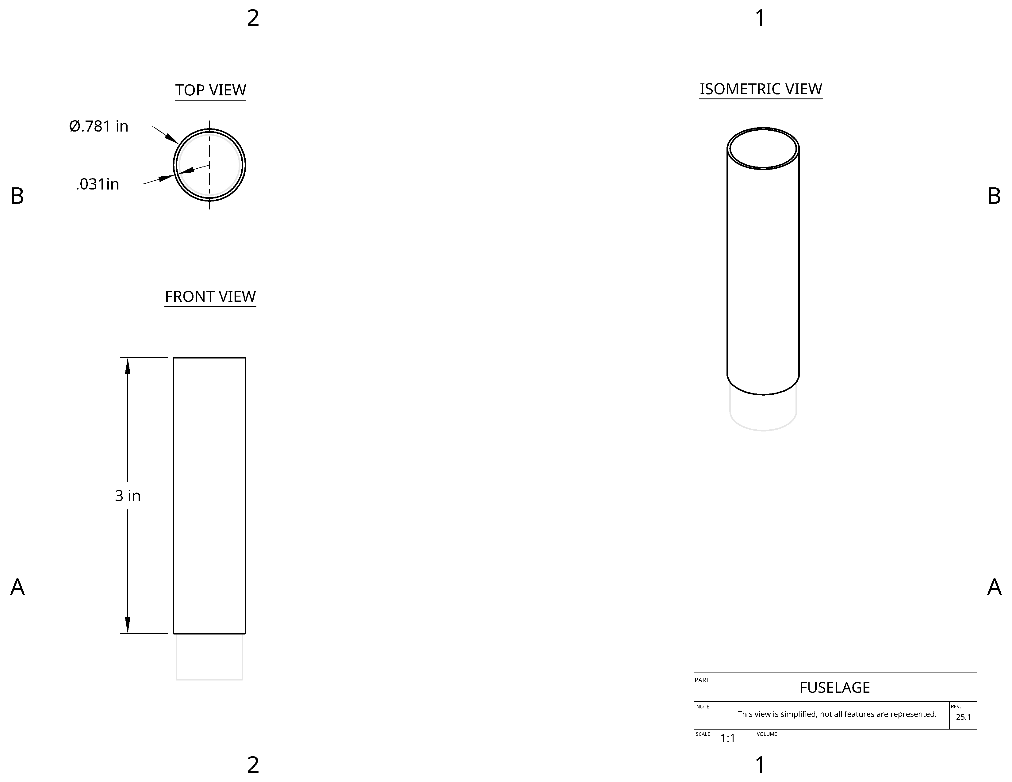
Dimension the outer body circle
- Select the dimension tool

- Consider this essential shortcut »
-
- The dimension tool is activated by pressing
d on the keyboard.
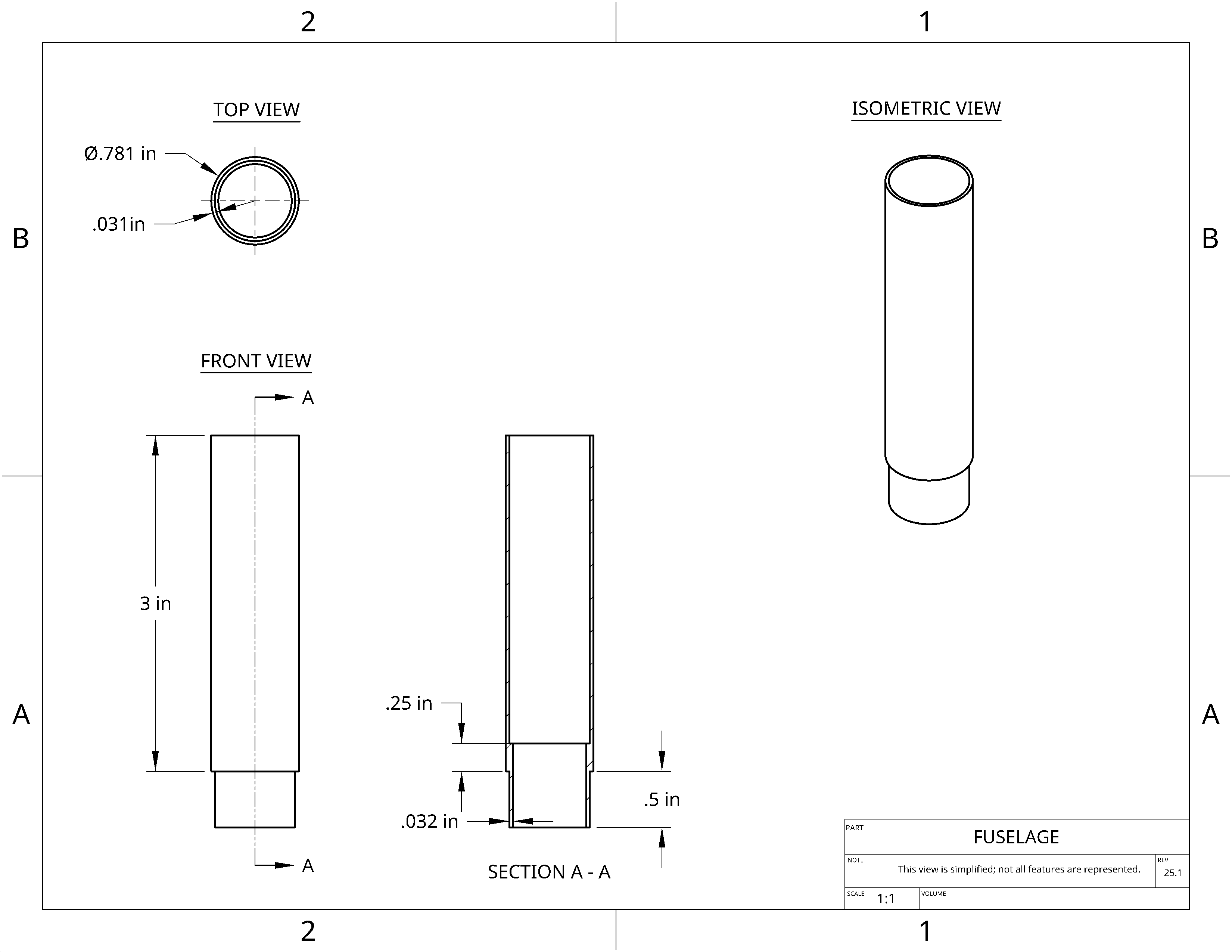
- Click on your circle and set its diameter to 0.781 in
- Press Enter to exit the dimensioning box
11.
Draw the inner circle
- Select the circle tool
- Draw a circle inside your first circle. Be sure to snap it to the origin.
- Select the dimension tool
- Click first on the outer circle and then on the inner circle
and set the difference between them to 0.031 in
12.
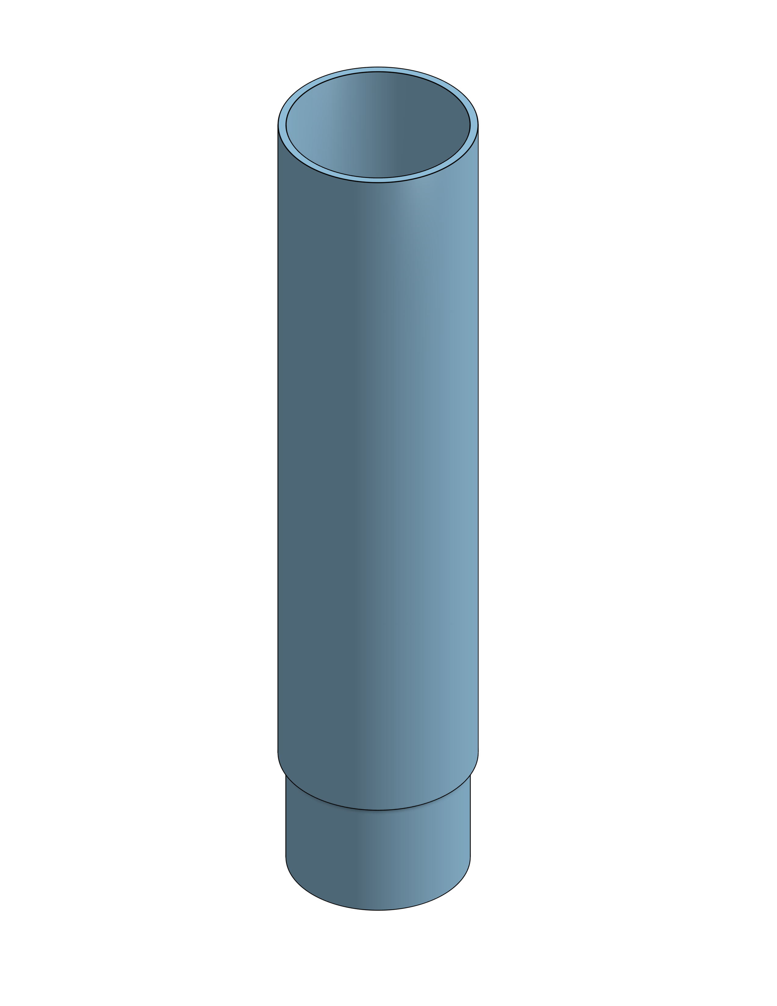
Extrude the body
- Select the extrude tool

- Feature shortcuts »
-
- Outside of a sketch, the keyboard shortcuts are usually
shift + [letter]. For example, shift + e for extrude.
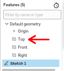
- Verify that "Sketch 1"
 is selected
- Set the Depth to 3.0 in
- Click the green check

13.
Change view to look at the bottom of the fuselage
- Hold the right mouse button to look at the bottom of the rocket
- Zoom in using the mouse wheel to get close to the bottom face
14.
Start a sketch on the lower stage connection tube
- Select the sketch tool

-
Keyboard shortcut »
-
- To enter a new sketch, press
shift + s.
- Click the bottom face of your tube to start sketching on that face
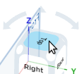
- Right click and select View normal to sketch plane to line up your view
-
Another keyboard shortcut »
-
- Pressing
n reorients the view to normal
- You can use this frequently after tilting and panning to reset.
-
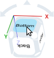
Is it upside down? »
-
- Click on the word "Bottom" on the rotation cube to turn it right-side-up.
15.
Finish the connector tube sketch
- Select the Use (Project/Convert) tool

-
Can't find it? »
-
-
Try the Search tools feature, type "Use" into the box.

-
You might have exited your sketch. Do you see a box that says "Sketch 2" and has a green check?
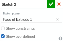
- If not, double click on Sketch 2
 to reenter your sketch
-
Keyboard shortcut »
-
-
Press
u for the Use tool (lowercase, no 'shift', since we're back in a sketch).
- Click on the inner circle
- That line will bold, as it becomes part of your sketch
16.
Finish the connector tube sketch
- Draw a smaller circle centered at the origin
- Dimension between the inner circle and the circle from the step above as 0.032
17.
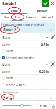
Extrude the connector
- Select the extrude tool
- Verify that "Sketch 2" is selected
-
Click on Add to add to your part instead of creating a new part

- Set the Depth to 0.5 in
- Check Second end position
- Set the second Depth to 0.25 in
- Click the green check
-
Didn't work? Part ended up different color? »
-
- Make sure you have the following set:
- Solid
- Add
- Sketch 2
- Merge scope: Part 1
18.
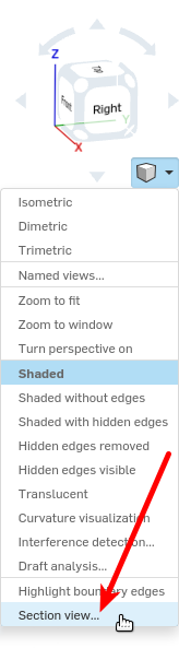
Turn on section view
-
We want to see inside the tube, so we'll have our view cut away part of the tube.
This does not change the part, just how we look at it
- Select the view menu

- Select "Section view..."
- Click on the Right plane

- Click the green check
19.
Fillet the body connector ring
-
What is a fillet? »
-
-
Fillet:
“a rounding of an interior or exterior corner of a part design.”
- We use fillets to round-out edges, which is especially useful when 3D printing.
- Select the fillet tool

-
Keyboard shortcut »
-
Since a fillet is a feature, not an element of a sketch, we press
shift + f.
- Click on the outside ring of the ledge
- Click the green check
Fuselage Tutorial
Previous
Page:
1
|
2
|
3
|
Next

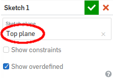
 plane.