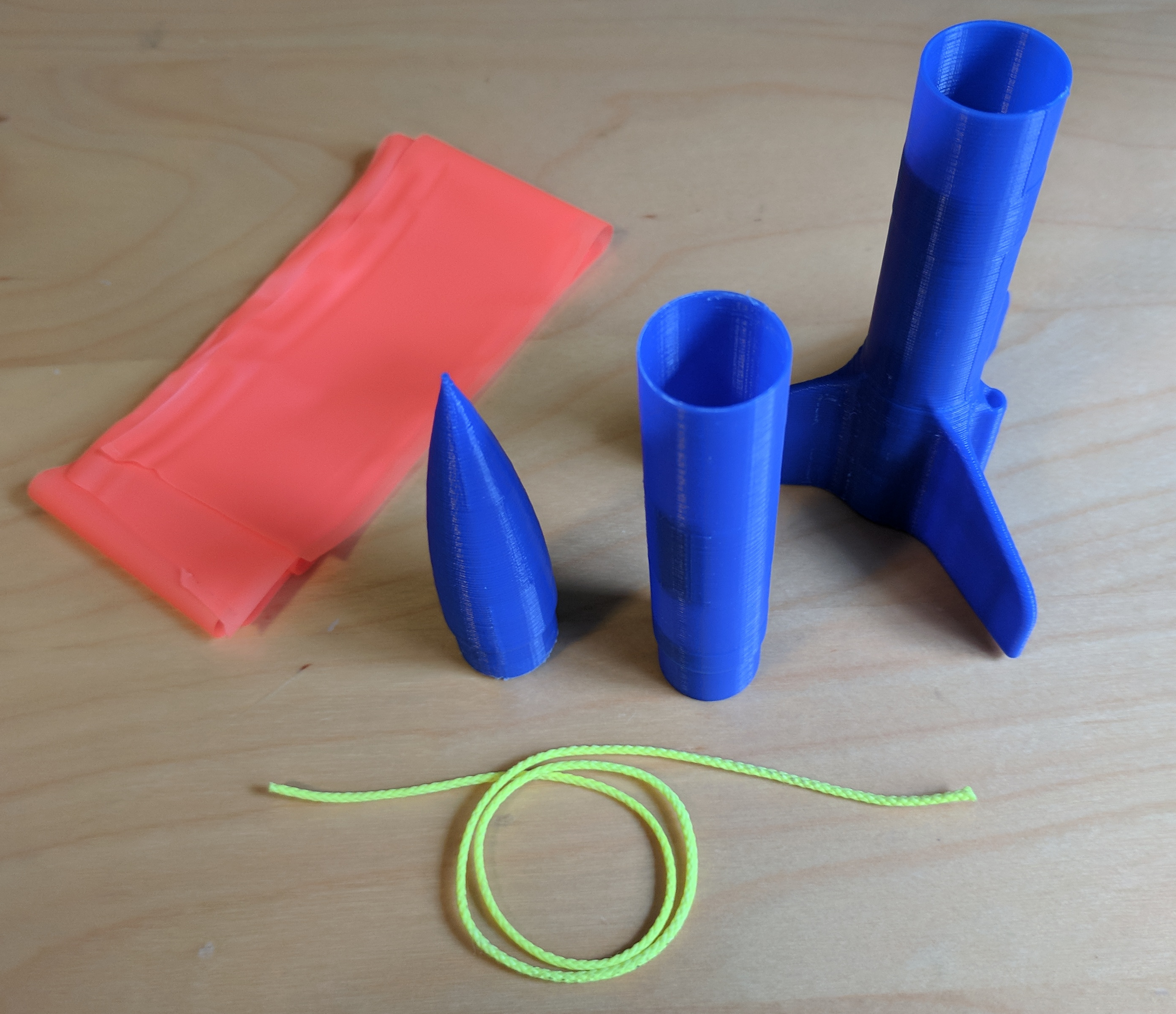
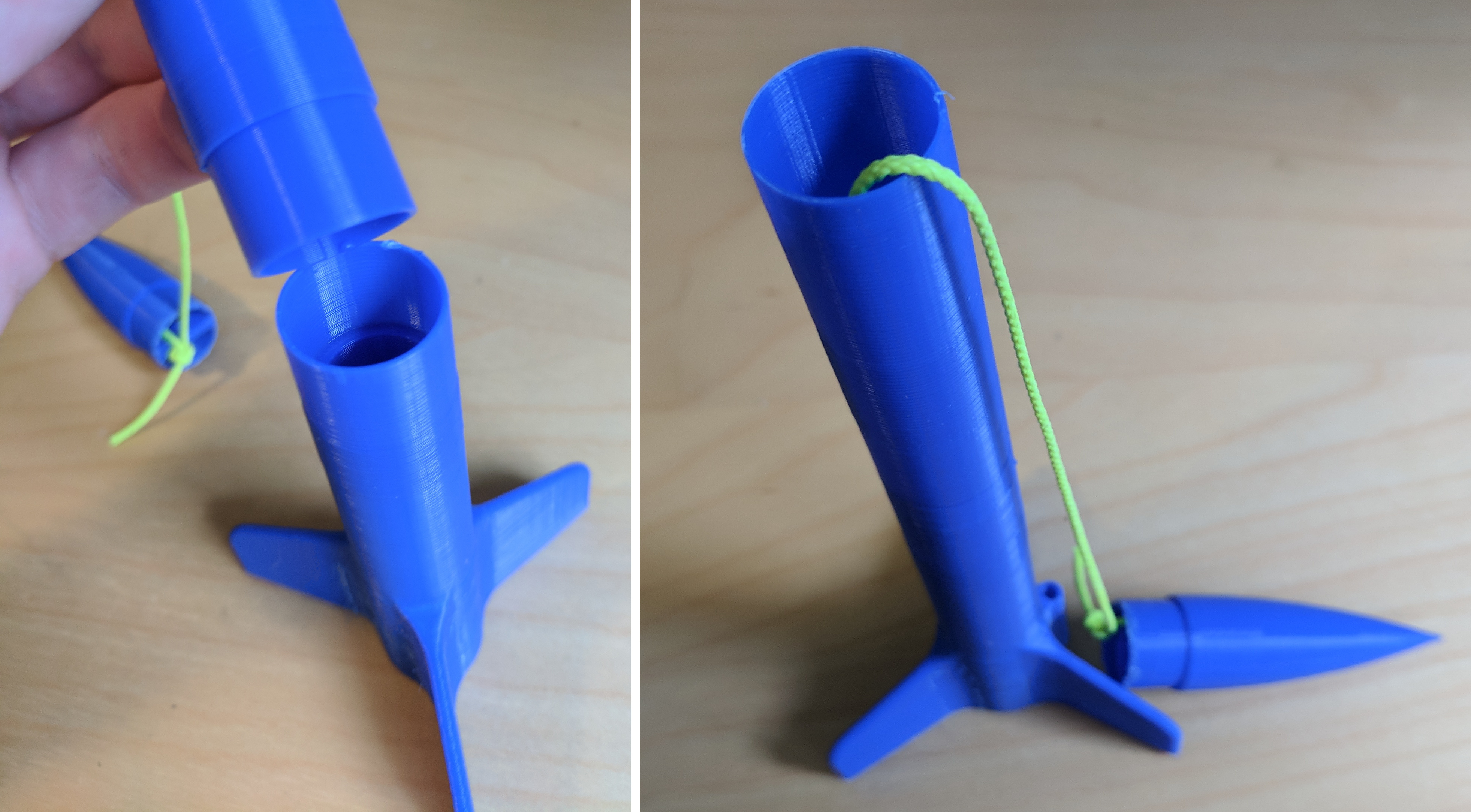
3D Printing

digital designs to physical reality

assembly-iso

3D Printng Workflow


assembly-iso


Export as STL


1. Export the fins+booster for 3D printing

  • Right click on the booster and fins
  • Select "Export..."
  • Select STL from the "Format" list
  • Set Units to Millimeter
  • Click OK
||

2. Export the fuselage for 3D printing

  • Right click on the fuselage
  • Select "Export..."
  • Select STL from the "Format" list
  • Set Units to Millimeter
  • Click OK
||

3. Export the nosecone for 3D printing

  • Right click on the nosecone
  • Select "Export..."
  • Select STL from the "Format" list
  • Set Units to Millimeter
  • Click OK
||


Slice


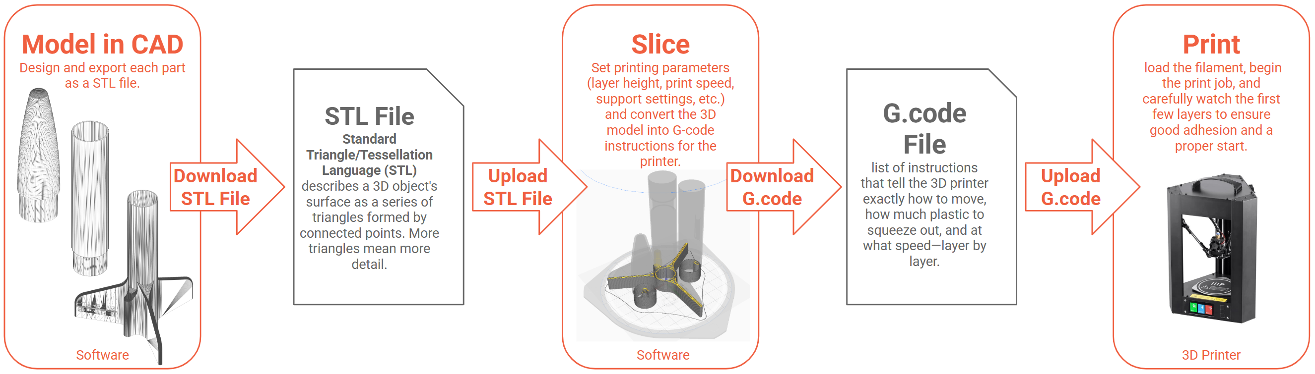
A slicer is software that slices 3D models (e.g., STL) into G-code instructions. It determines nozzle movements, material extrusion, and speeds. Adjusting its settings affects print time, part strength, and appearance.

Popular Slicer Software

All slicers share a similar workflow, though the interface and features may vary.

4. Select the 3D printer

||
  • Select Add printer
  • Look for a profile that matches the model of your 3D printer.
  • Make sure the build volume and nozzle size are accurate.

5. Choosing the Filament

||
  • Check the filament spool label to confirm the type.
  • Common types: PLA, ABS, PETG, or TPU.

6. Upload the fins-booster.stl

||

7. Upload the fuselage.stl

||

8. Upload the nosecone.stl

||

9. Move the fuselage closer to the fins+booster

||
  • Speeds up printing by reducing travel
  • Minimizes stringing between parts
  • Optimizes bed usage
  • Allows shared supports

10. Move the nosecone closer to the fins+booster

||
  • Retains heat in the part
  • Improves inter-layer adhesion
  • Reduces warping risk

11. Inspect the parts

||
  • Ensure all parts are on the build plate
  • Check that no parts overlap

12. Set the print settings

||
  • Each 3D printer requires individual tuning.
  • These are the most important settings:
    • Layer Height »

      Determines how thick each layer is. Thinner layers yield smoother surfaces but take longer; thicker layers reduce print time but may show more lines.

    • Print Speed »

      Controls nozzle movement speed. Faster speeds shorten print time but can reduce quality; slower speeds increase detail but take longer.

    • Infill Density/Pattern »

      Sets how solid the part is inside. Higher infill strengthens parts but uses more material and time; lower infill saves both but weakens parts.

    • Shell/Wall Thickness »

      Adjusts the number of perimeter lines. Thicker walls improve durability but take longer; thinner walls save time and filament.

    • Support Structures »

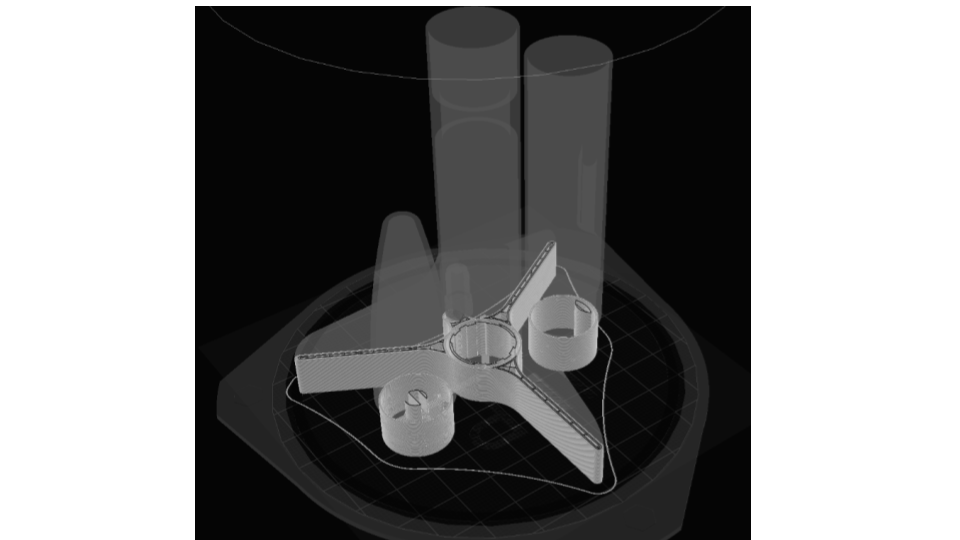
      Temporary material for overhangs or complex shapes, improving print success but requiring removal afterward.

    • Bed Adhesion (Raft/Brim/Skirt) »

      Methods to help the first layer stick. They prevent warping or detachment but add extra material and print time.

    • Temperature Settings (Nozzle/Bed) »

      Proper temperatures ensure filament melts and bonds correctly, preventing warping or under-extrusion.

13. Slice the part

||
  • Slicing is the process of converting a 3D model into layers and generating instructions (G-code) that the printer follows.

14. Preview the sliced part

||
  • Look for overhangs, weak points, or collisions.
  • Check layer lines for gaps or missing geometry.
  • Ensure supports are placed correctly for complex shapes.
  • Confirm the part orientation and infill settings are accurate.

15. Download the G-code

||


3D Printer Setup


  1. 16. Transfer G-code: Load the file generated by your slicer (via SD card, USB, or Wi-Fi) to your 3D printer.

  2. 17. Bed Adhesion: Clean the build surface, level the bed, and apply any adhesive needed for proper first-layer sticking.

  3. 18. Preheat: Heat the nozzle and build plate to the recommended temperatures for your filament.

  4. 19. Load Filament: Ensure the filament is inserted and purged of any previous material.

  5. 20. Start Print: Begin your print job and monitor the first few layers to check for proper adhesion.

  6. 21. Cool & Remove: Allow the part to cool, then gently remove it from the build surface to avoid damage.

  7. 22. Post-Process: Remove supports, sand, or paint as needed for a finished look or functionality.

Assemble Parts


23. 3D print the files and gather parts

24. Start assembling the rocket

  • Thread a flame-resistant string or shock cord through the tube inside the fuselage

25. Tie the string off on the bottom end with two knots to keep it from coming out

26. Tie the other end around the bar in the nosecone

  • You can use tweezers or a paperclip to get at the string when it's inside the nosecone.

27. Push the fuselage into the lower body. It should be a very tight fit to keep it from coming loose in flight.

  • Depending on your printer, you might have to sand a little bit off or put a piece of tape on the side to get the perfect fit.

28. Tie a streamer or parachute to the string

29. Roll the streamer and push it into the fuselage

30. Slip the nosecone on. It should be a loose fit so that the ejection charge will pop it off.

  • Depending on your printer, you might have to sand a little bit off or put a piece of tape on the side to get the perfect fit.

31. Load an engine (A, B, or C-class)

32. Go flying!

||