-
Keep It Neat »
Make sure all lines and letters are clean, clear, and easy to read.
-
Use the Right Scale »
Draw objects so the size on paper makes sense compared to the real object.
If something is too big or too small, use a scale that keeps your drawing readable.
-
Label Everything Clearly »
Every important part of your drawing (like lengths, widths, or heights) needs
a clear dimension so others know exactly how big things are.
-
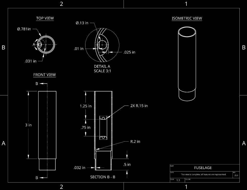
Use Standard Symbols and Abbreviations »
Engineers often use common symbols (like Ø for diameter). Using these standard
symbols and abbreviations avoids confusion.
-
Stick to Standard Line Types »
Different lines can mean different things: solid lines for visible edges,
dashed lines for hidden edges, and so on.
-
Include Multiple Views »
Show objects from the front, top, and side if needed. More views help people
understand the shape and details of your design.
-
Add a Title Block »
A small box on your drawing can list the part name, who drew it, the date,
and any important notes.
-
Use a Neat and Consistent Font »
Your text should be easy to read and look the same across your entire drawing.
-
Provide Enough Dimensions, But Not Too Many »
Give all the measurements needed to build or understand the object.
Too many repeated dimensions can be confusing.
-
Check for Accuracy »
Make sure your measurements and labels are correct. Even small errors can
cause big problems later.
-
Highlight Important Details »
If something is critical (like a small hole or a special cut), make a note
or add a close-up view to show it clearly.
-
Follow Drawing Standards »
Different companies or groups may have specific rules on how drawings should look.
Follow them so everyone's drawings match.
-
Keep Track of Changes »
If you make updates, note what changed and when (known as a revision).
This helps everyone know which version is current.
-
Use Section Views When Needed »
“Cut” your object in the drawing to show what the inside looks like.
This helps people understand holes, grooves, or other hidden features.
-
Ask for Feedback »
Share your drawing with others to find mistakes or confusing spots.
Fixing